A Spatial Conceptual Model
Notice that this tutorial does not focus on generating a conceptual design for a given set of requirements, but on the use of the MDA to transform a conceptual model into a physical database model. As such the initial conceptual model (PIM) is predefined in advance. The tool chosen for this tutorial is called Enterprise Architect or EA. You can install EA through the ITC Software Manager.
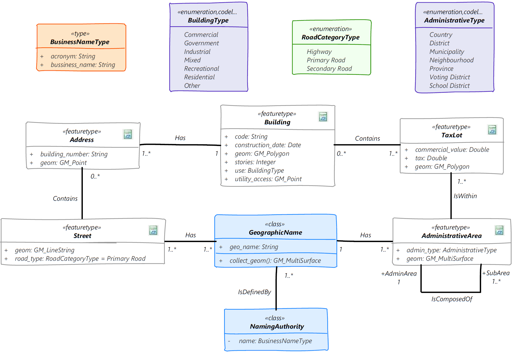
To start with the tutorial, we will need a small UoD to be used as the basis of the model to be transformed. The list below presents a summary of the requirements behind the conceptual model used in the tutorial. The model reflects the needs of a government organization that manages administrative data as follows:
UoD – Administrative boundaries system
- A country is divided into administrative areas of different types, e.g., regions, provinces, municipalities, districts, neighborhoods. These administrative areas are structured in a hierarchy, for example, a province is composed of municipalities. Administrative area may not necessarily be contiguous areas. All administrative areas are known by an official name.
- The registration of parcels and buildings is used for taxation purposes. Parcel boundaries fall within a single municipality. Buildings on the other hand are parcel or tas lot independent and can fall within multiple parcels. Taxes on buildings are calculated based on the building’s use, e.g., commercial, industrial, residential.
- Businesses and individuals are registered through addresses. There could be multiple addresses on a single building. Addresses are not only used for registration, but also for routing and car navigation.
- All official names are defined by an authority which is known to the public by its business credentials.
What we have done here, is to develop a PIM (Platform Independent Model) to describe our Universe of Discourse (see 1) using ISO standard data types. We will use this model trough the tutorial and transform it. The PIM model will be transformed into a PSM (Platform Specific) model using, as the platform of choice, PostgreSQL/PostGIS. Then, we will transform the resulting PSM model into actual SQL code for the creation of the physical structure of the database in PostGIS.
Enterprise Architect
First things first, we need to make sure that Enterprise Architect (EA) is configured properly to use the profile with the required spatial data types. Let us get to work. Start by creating a folder in your computer to store the files used or generated in the exercise. Next, start EA. If the Manage Projects window appears, simply select cancel for now. Later on, you can use this window to select the specific project file that you want to work with (right now we do not have one). EA comes pre-configured to create standard UML models and some other, more specific, model types. EA is not configured out-of-the-box to develop spatial database models like those we are interested in.
As discussed in the previous section, when we need to extend the standard UML to suit our modelling needs, we create a profile. For our spatial database design, we have created a profile which contains the additional modeling elements that we need. We only need to tell EA that we want to use this profile. There are a few options to go about this in EA, one of them is called MDG Technologies. An MDG Technology in EA, corresponds to an extension package that contains customization elements including, a.o., UML profiles. We have a profile available (see 2); it only needs to be added to EA.
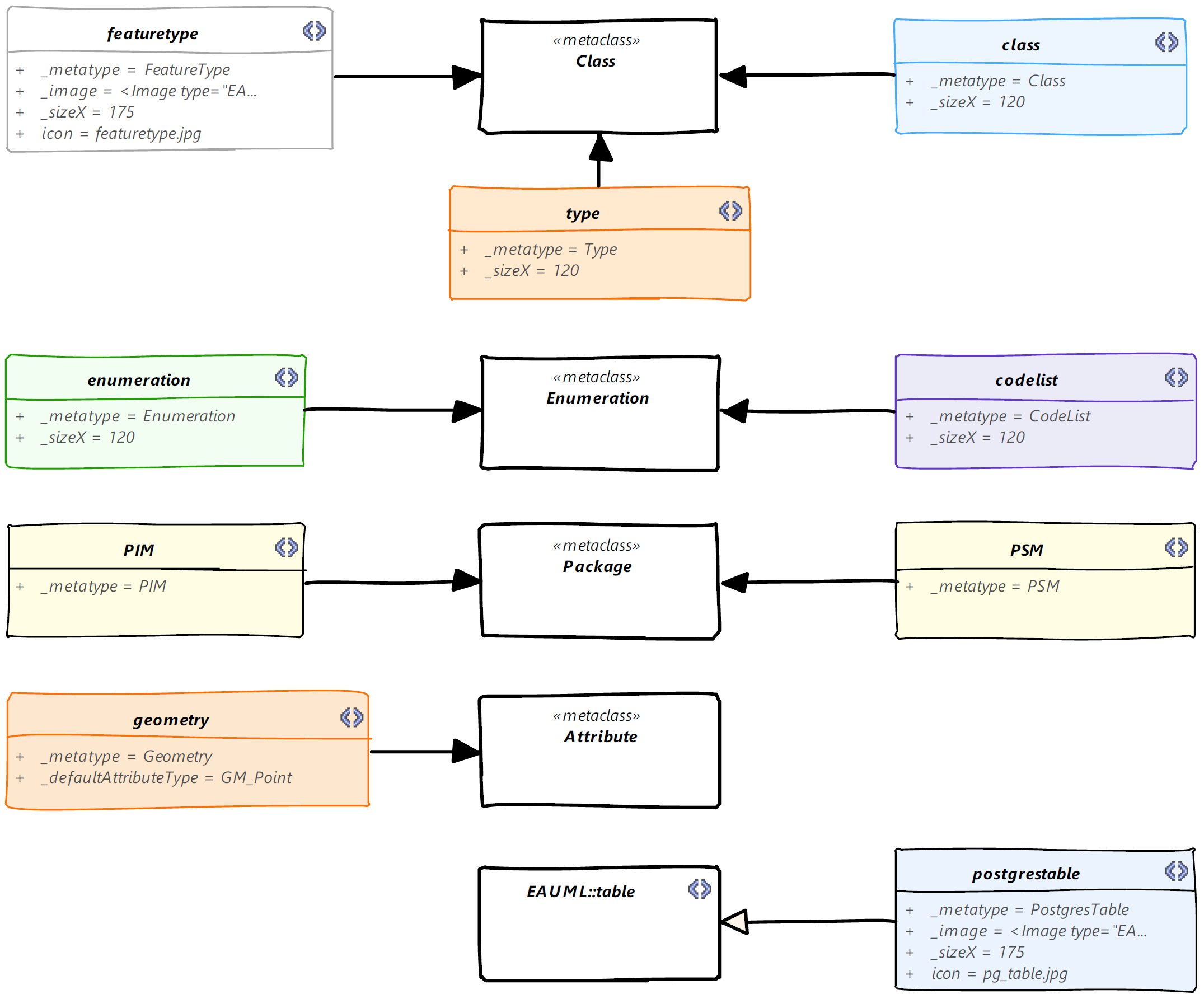
To incorporate spatial database design concepts in EA, we have created an MDG Technology that contains 1) the spatial database design profile, 2) the transformation rules from PIM to PSM, and 3) a couple of diagram types used to configure the user interface. The MDG Technology is called MDA - Spatial Database Design or MDA-SFS for short. The MDA-SFS configuration files are available through a URL from one of the ITC’s servers.
To add the MDA-SFS profile as an MDG technology to EA, select the Specialize ribbon and then click on the Manage-Tech icon (the left-most one, which appears in the Technologies subsection of the ribbon). A window appears with the list of the current technologies available in EA. You can enable or disable them if required. To include a new technology, we only need to specify the location where its configuration files are located. To do this, click on the Advanced button, then click on Add → Add URL. In the URL input box, type (paste) the address shown below. Then click OK twice to accept the registration.
Simple feature UML profile URL:https://gip.itc.utwente.nl/exercises/docs/spatial_databases/profile/MDA-SFS_Profile.xml
At this point you should be able to see the MDA-SFS technology in the list. You can click on it to see its detailed description. Make sure that the check box is selected and then click OK to finish this step. Note that the term “MDG Technology” is purely an EA feature. It is one of the ways in EA to handle UML profiles and has nothing to do with the modelling process itself. The actual process of creating a UML profile falls outside the scope of this exercise. The new profile will be available for you in any successive sessions of EA, you do not need to repeat this step in the future when creating other models.
This step is required only once. From now on the installed version of EA in your machine will be able to use the simple features spatial profile in the creation of models.
The EA Project File
We can now start with the definition of new projects making use of the MDA-SFS profile. Create a new project, by using the Create new project option, give the project file a name and make sure it is located (saved) in your work directory. Using the Project Browser panel on the left of the screen, right-click on the Model element and select Add a Model Using the Wizard to create a PIM Model.
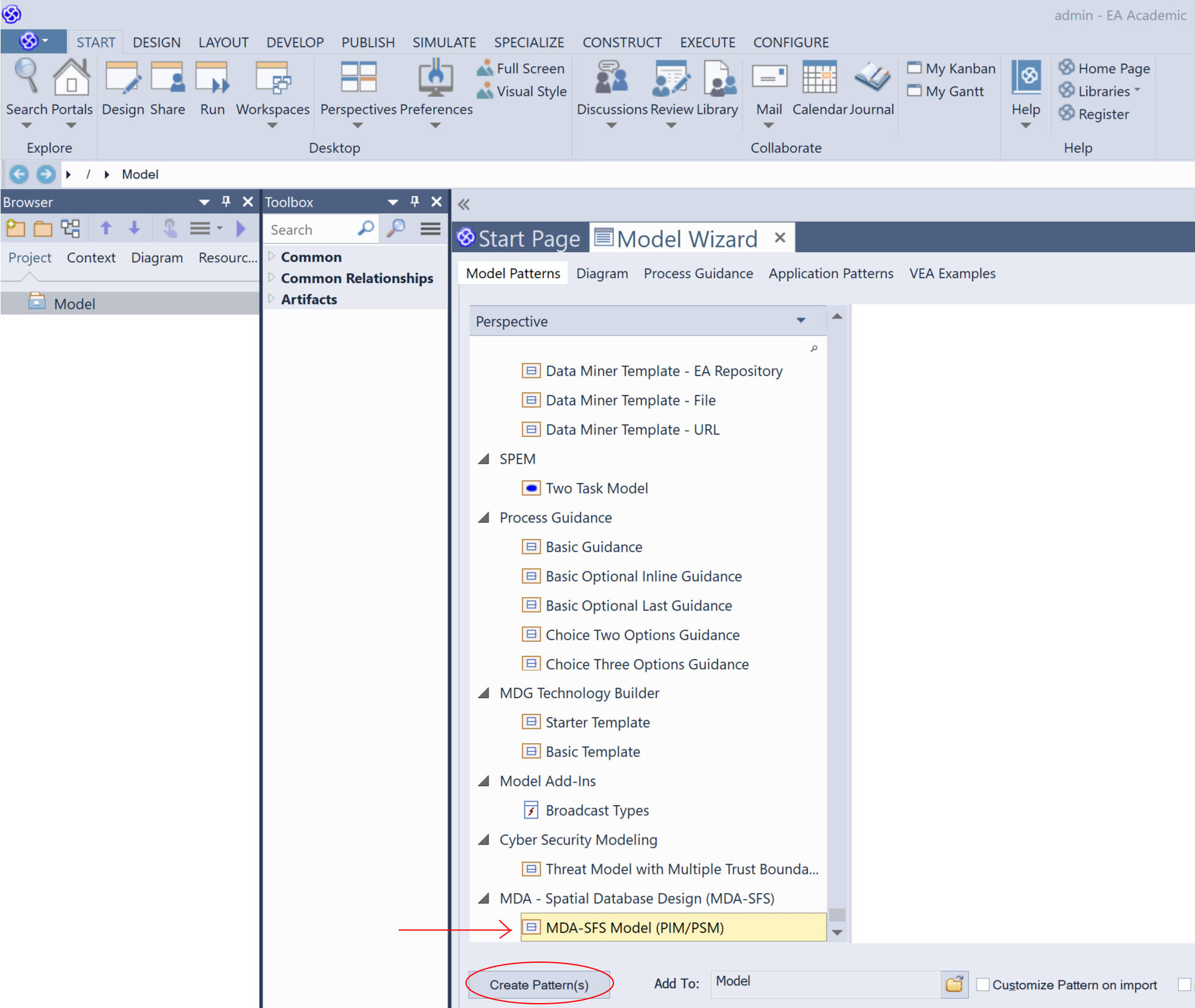
The various types of diagrams in EA are organized according to perspectives, and there are many. You can scroll all the way down to find the MDA-SFS patterns. Or, on the top-right of the EA window, click on the Perspective header and then select Specialized → All Specialized. Now, you should see a shorter list, select MDA-SFS Model (PIM/PSM), and then click on the Create Pattern(s) button to create your base design components (see 3).
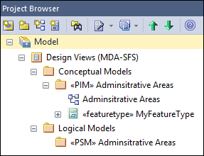
To the left of the interface, in the Project Browser, expand the Design Views (MDA-SFS) to see its contents. There should be two views: Conceptual Models and Logical Models.
We now proceed by creating a package to contain the modelling elements of our exercise. In the Project Browser, right-click on the My Schema package, and select Properties. Type a name, Administrative Areas. Do the same for the My Schema diagram. Your project browser should look like 4 at the moment.
We also need to specify the default data types for both conceptual design (PIM) and logical design (PSM) within EA. This is done through the Code Engineering toolbox. To enable it, select the Portals option (left-side of the ribbon), then select Show Toolbar, followed by Code Engineering. On the newly displayed toolbar, specify the default data types, select ISO General Feature Model as the default code language (left), and PostgreSQL for the default database type (right).
To start creating model elements, open the Administrative Areas diagram of the PIM package and use it to recreate the model shown in 1. Double-click on the diagram to open it. To produce your model, select the appropriate modelling elements from the PIM-Elements toolbox and place them in the diagram canvas.
Make sure not to use spaces in any of the elements’ names. Notice that literals in enumerations and code lists are entered as if they are attributes but without a specific data type, instead, make sure that the Is literal checkbox is selected for each of the literals. When defining attribute types, do not type or enter values in the Type cell of the attributes dialog box. Instead select the appropriate type from the drop list. If the type that you are looking for, does not appear in the list yet, e.g., RoadCategoryType, then you need to create the type first, by selecting the correct element from the toolbox. Another reason for the data types that you need not appearing in the list is that you did not select the proper platforms in the Code Engineering toolbar.
The stereotype names in your diagram might look slightly different to those on 1. This is because you might be using a newer version of Enterprise Architect which results in different visual settings to those used during the generation of the figure.
Do try to understand the model based on the described UoD, and if necessary, make modifications to it. Pay attention to the classes with geometric attributes. Explain the mechanism used to model administrative areas, such as state, province, etc. Your understanding of the PIM model is required so that you can make sense of the transformations that will be executed next.